Measuring Guide
How to measure for your awning.
We supply the awning and you arrange the installer, so getting the measurements right up front is what makes the whole thing work. Ten minutes with a tape measure and a phone camera is usually all it takes.
Not sure? Send us your photos and rough measurements and we will work it through with you before you order. Final measurements remain your responsibility, so have your installer confirm them before you commit.
Step 1
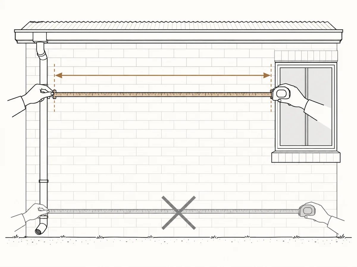
Measure your available width at the mounting height
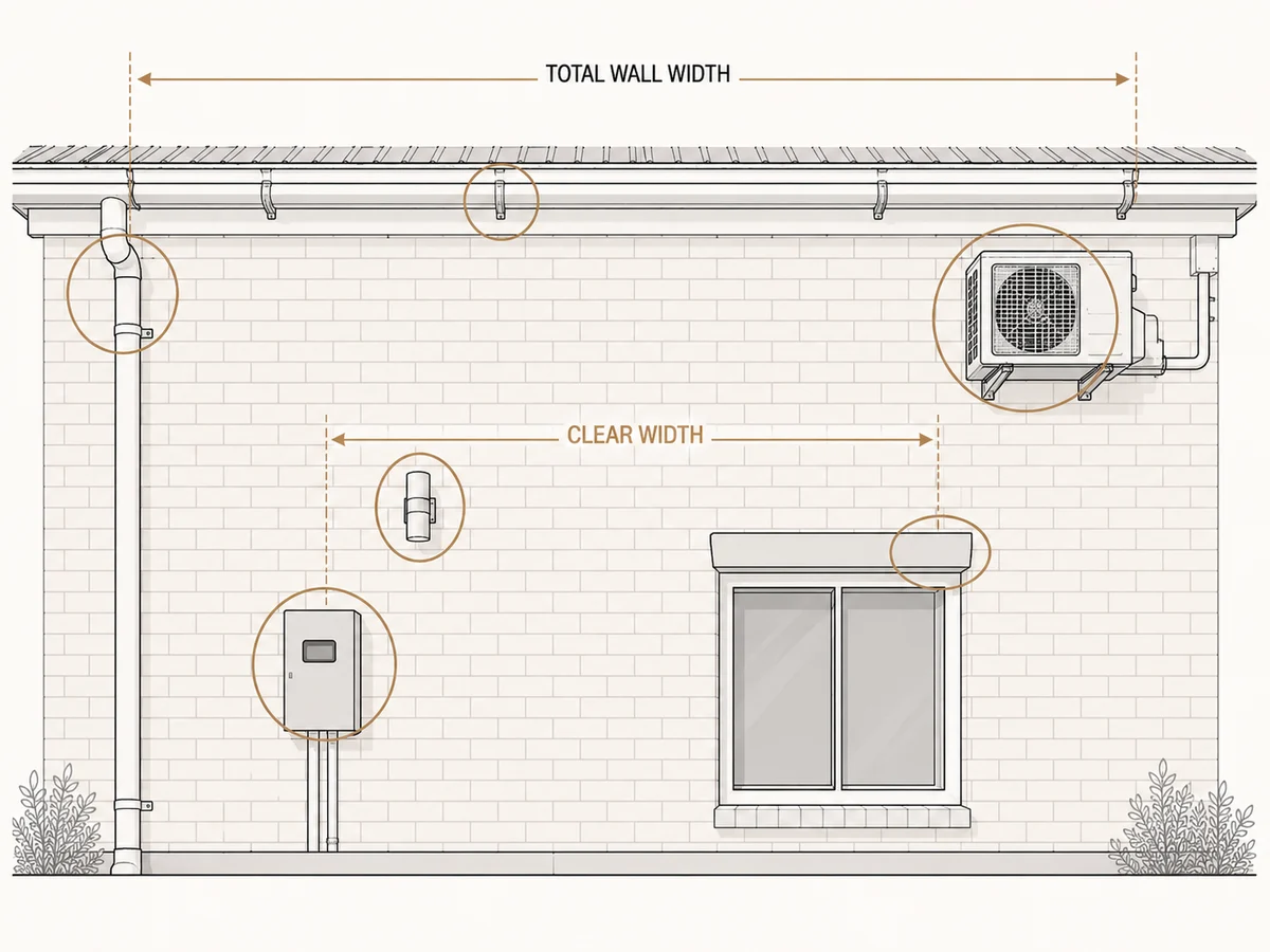
Measure the clear width of the wall at the exact height the awning will be mounted, not at ground level. Walls are rarely clear the whole way up: downpipes, light fittings, gutters, meter boxes and window heads all reduce the usable width at head height even when the ground looks open.
Write this figure down. Everything else is checked against it.
Minimum installable width
(left base + retracted arm length) + (right base + retracted arm length) + 16 cm
The retracted arm length depends on the projection you choose - see step 2. If your available width is less than this figure, the awning will not fit at that projection.
Clearances
- At least 8 cm clear at each end of the cassette.
- Allow 6.5 cm from the end of the cassette to the outer bracket position.
- At least 10 cm clear of any internal or external corner, so the masonry does not crack.
- At least 5 cm between the two folding arms without a centre bracket.
- At least 10 cm between the arms with a centre bracket fitted. The centre bracket itself is 5 cm wide.
Step 2
Work out your projection, and check the fall
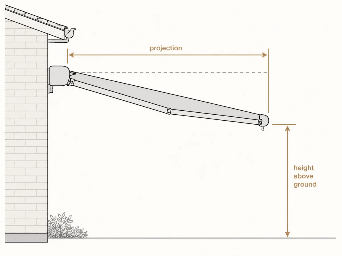
Projection is how far the awning reaches out from the wall. The longer the projection, the longer the arms are when folded away - which is what drives the minimum width in step 1.
| Arm projection | Retracted arm length |
|---|---|
| 1.0 m | 0.76 m |
| 1.5 m | 1.04 m |
| 2.0 m | 1.32 m |
| 2.5 m | 1.54 m |
| 3.0 m | 1.85 m |
| 3.5 m | 2.05 m |
Check the fall. An awning is pitched, so it drops as it extends: the front bar sits lower than the cassette. Measure the height at the front bar at full projection, not just at the wall, and make sure paths, doors and windows stay clear.
Step 3
Check mounting height, headroom and door swing
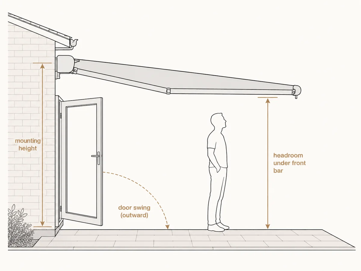
Decide the mounting height, then check the clearance at the front bar at full extension before anything is fixed. Because the awning falls as it extends, the lowest point is at the front bar, furthest from the wall.
- Will people walk under it comfortably at the front edge?
- Do doors and windows still open fully, including outward-swinging and bi-fold doors?
- Is there room above for the cassette itself, clear of the gutter or eave?
Step 4
Identify your wall type
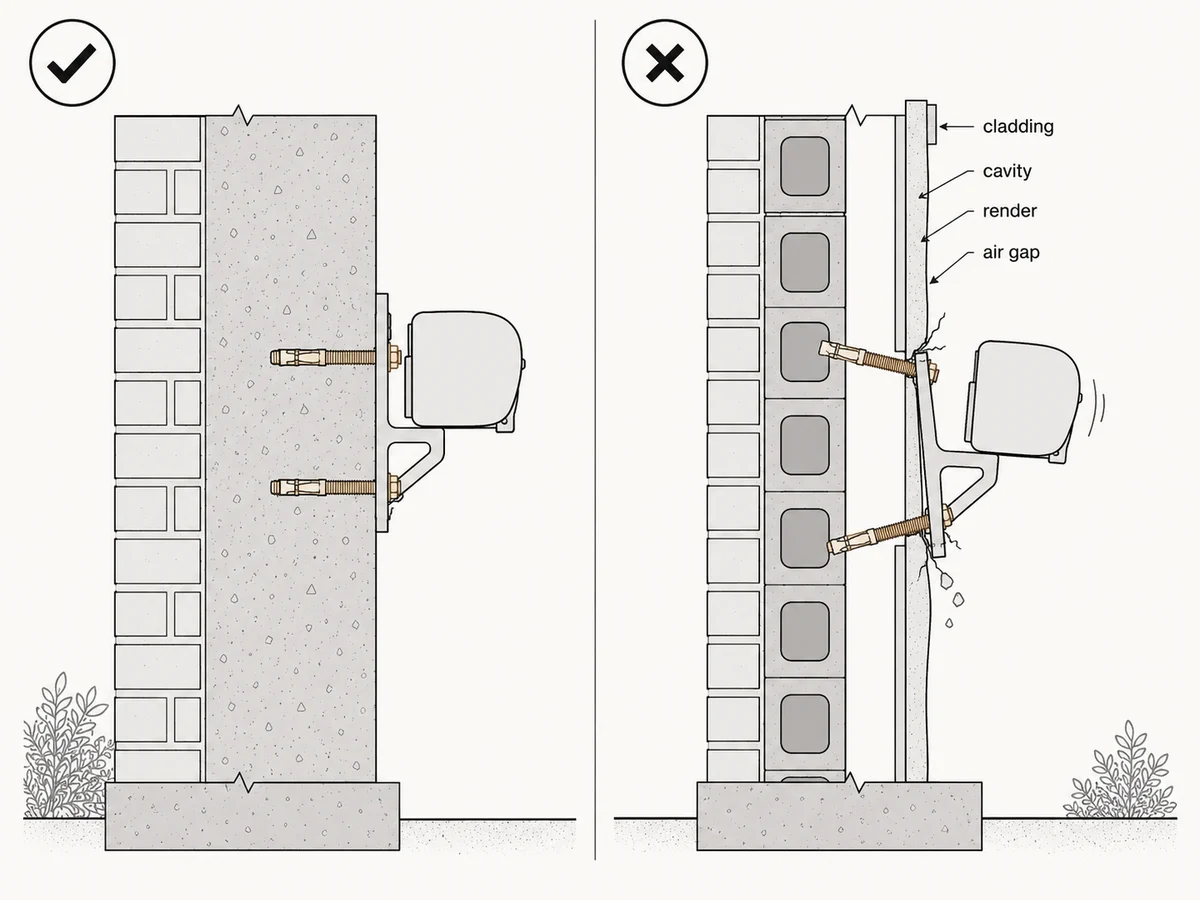
This is the step people skip, and it is the one that causes failures. The awning is heavy and everything hangs off two brackets (three from 4 m wide), so the anchor at each one has to reach something that can carry it. Your wall type decides which anchor that is.
Which anchor for which wall
- Concrete, solid brick, structural timber - The supplied anchors, straight in.
- Hollow or cavity brick - A chemical anchor with a sieve sleeve, so it engages the structural leaf rather than the void.
- Rendered or clad walls - Fix through the surface into the structure behind it. Drill a small pilot hole first to confirm what is there.
- Mud brick, or a wall you cannot identify - Get engineering advice before drilling.
The diagram shows the failure to avoid: the same bracket, fitted with a solid-wall anchor into a cavity wall, pulls out under load. The right anchor for the wall is a few dollars at any hardware store.
Step 5
Check for obstructions
Walk the wall at mounting height and note anything in the way. Each of these either reduces your usable width or needs relocating before installation:
- Downpipes
- Gutters and gutter brackets
- Light fittings and sensors
- Meter boxes
- Window heads and reveals
- Air conditioning units and pipework
Photograph anything you are unsure about. It is far cheaper to shift a downpipe on paper than after the awning has been made to a width that does not fit.
Step 6
What to send us
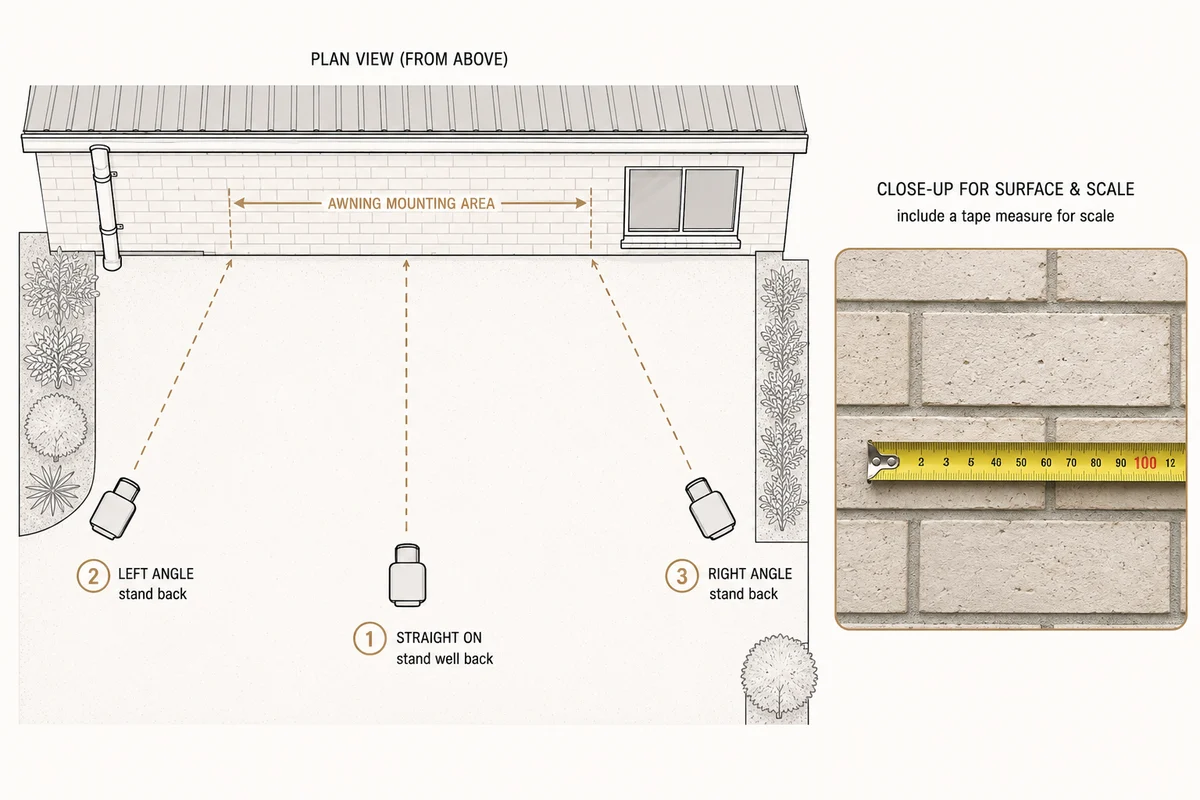
Photos - taken in daylight, with the whole area visible:
- One straight on to the wall, standing back far enough to see the full width
- One from each side at an angle, showing corners, downpipes and the eave
- A close-up of the mounting area, showing the wall surface and anything fixed to it
- A photo of anything you are unsure about, with a tape measure in shot for scale
Measurements - in centimetres or millimetres, stated at mounting height:
- Available width at the mounting height
- Distance to the nearest corner at each end
- Intended projection
- Mounting height from the ground, and the height of any door or window head below it
- What the wall is made of, if you know
Figures on this page are taken from the installation manual supplied with the awning. Where this guide and the manual differ, the manual applies. ASG is supply only - we do not attend or assess sites, and responsibility for final measurements and for the suitability of the structure rests with you and your installer. Information for your installer.